Pic of the Kit
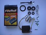
Purpose: To remove the continually wearing / needing adjustment parts and replace the Points and Condenser located inside and outside of the distributor with a optical sensor and timing module which has no wearing parts.
Difficulty: Medium - Needing a basic Knowledge of the ignition system of a mighty boy, hand tools and timing. Remember this is a small parts job and a little fiddly instructions should give a good direction but a little assembly and re-assembly to get everything sitting right might be required.
Disclaimer: This is my process and understanding of the instructions provided by crane cams to install on a Suzuki mighty boy, all original instructions should be read understood and followed first.
Tools needed: Screwdrivers, Stanley knife, black silicon (engine or sika-flex), spanners, crimpers, crimp lugs, rags and workbench.
Parts Needed: Red Flat crimp lugs, Red round 5mm Crimp lugs, xr700 kit $200, su12 (non resistive Coil super-cheap) $40ish, black Silicon (i used engine sealant $6.00), new rotor button and cap leads and plugs
1) Disconnect the battery
2) Remove the ignition leads from the cap taking note of which is which cylinder
3) pop the dizzy cap off and using a black texter mark direction of the rotor on the side of the dizzy and mark a line so you know roughly where it was positioned when the timing was set.
4) undo the bolt retaining the dizzy
5) remove the wire running from the internal of the dizzy to the negative of the coil (this will not be re-used) and remove the vacuum line running to the vac advance
6) pull the dizzy from its home and place a rag over the hole it just came out of.
7) placing the dizzy on the workbench set about removing the condenser on the side, 1 screw holding it on
8 ) the rotor button will pull straight off and remove the points by undoing the 2 screws
9) the vacuum advance canister has a small screw retaining it on the side and internally to the dizzy has a small c clip which holds onto the advance plate (i used a small screw driver and pushed it off be careful they like to fly off)
10) the advance plate will need to also come out this is done by loosening the 2 screws on either side and lifting straight up
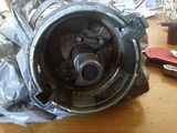
11) you should now have a empty dizzy looking like this pic above
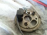
12) with the advance plate removed find the little bracket and the optical sensor from the kit
13) install the little bracket using one of the screws from the points module and then laying the optical sensor on top position so that the leads out will head the direction of the hole the points wire was running through. leave loose you will need to adjust when the disc is placed on later
14) find the little 6 cylinder trigger wheel (bottom left one in the kit pic)
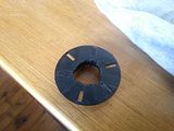
15) we need to black out the 3 unused slots not going to be used (if they stay open the ark will jump and cause havoc - mid timing), this is done using a thin layer of black silicon just smeared into the slots. wait till dry and trim. Make sure you do the right slots. there is a 3 face key-way the points used to travel along this is what the trigger wheel will mount on.
16) re-install the advance plate and vacuum module (2 screws inside, 1 screw on the body and the little c clip on the arm) this is a good time to tighten the bottom little bracket using the original screw
17) now the optical sensor should still be loose on the top screw just move it to the side and feed the 3 wires out the little hole
18) a little bit of the plastic might need to be removed on the inside of the trigger wheel where it sits on the shaft but it should now just slide on and be fairly tight
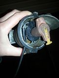
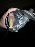
19) moving the module back into place leaving an equal gap top and bottom of the trigger wheel and clearance so it can spin, (it should look more like this Above and below) tighten the little screw and make sure to leave enough slack for the wire to move without getting caught on advance and normal position
here it is from the other side
and again
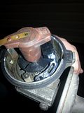
20) replace the rotor button and put a little silicon around the hole the wires run through to stop water ingress
21) this is where we need the marks to re-align the dizzy back into place and the direction of the rotor button. ( the gears on the end of the shaft will cause the rotor to spin as it goes in, you need to make allowance for that as it goes in.
22) replace the cap and re install the leads
23) Wiring, installing the module and replacement of the coil is the next thing
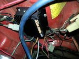
24)I mounted the module on the passenger side strut tower using some existing holes and facing the little led upwards.
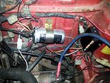
25) remove the old coil and replace with the su12 ( 2 types of coils 3 wire and 2 wire) 3 wire has and extra direct power feed switched while cranking from the starter, and the standard ignition switched power running from the fuse box and an earth through the dizzy (mine also had a brown wire i just isolated it)
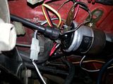
26) the 2 power wires go to the + side of the coil
27) New wiring consists of 3 wires running to the dizzy which are colour coded and correspond to the 3 wires running from the optical sensor, also 3 wires to the coil red yellow and black.
Red = goes to the + side of the coil
Yellow = goes to the -ve side of the coil
Black = find a nice earthing point on the firewall and run to that
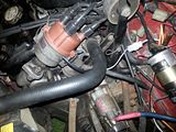
grey/white/black these 3 go into the corresponding opposite of the molex pin and just plug in, colour for colour.
Fireball Wiring Diagram
(Note this is an external dropping resistor set up and will not be needed if just using a 3Ohm coil)
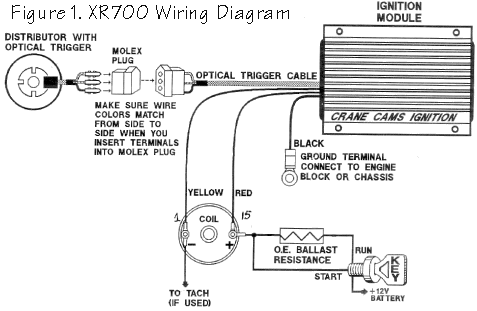
28) cap on replace any leads and give everything a good clean up (time to do new plugs and leads if you havent already)
29) Because everything lined back up pretty well it should fire straight up, then chuck a timing light on and set it back to 7 atdc for a f8b or 10 atdc for a f5a
THIS MUST BE DONE MINE WAS 20 DEGREES OUT WITH MINOR ADJUSTMENT
Things i found doing this:
*the standard 3 pin coil has an internal ballast resistor on the ignition switched side of the coil to limit the current unless cranking
*the module paperwork states it must be used with a ballast resistor(1.6ohm) to limit current if using a 1.5Ohm coil, i used a non resistor coil (3Ohm) doesn't get hot and runs fine, although might take a little more to start i havent noticed it because it is that much better.
*when making adjustments to the timing slight adjustments make a HUGE difference now
*the negative side of the coil- you can run a wire to an aftermarket tacho for the trigger signal
